- Virtuoso main window looks as follows.

- Choose 'File' -> 'Import' -> 'Stream...', then 'Virtuoso(R) XStream In' window will appear as follows.

- Choose a gdsii file in 'Stream File'.
- Choose myDesign in 'Destination Library'.
- Click 'Load File' then a cell will be shown in 'Top Cell'.
- Choose your design name in 'Top Cell'. The design name is what you typed in 'GDS Structure Name' in Encounter.
- The window should look like the following.

- Click 'Translate'. There must not be any error during translation.

- If you meet warning messages as above, just click yes.
- Click 'Cancel' in 'Virtuoso(R) XStream In' window to close it.
- Choose 'Tools' -> 'Library Manager...' in Virtuoso main window then Library Manager window will appear as follows.

- Choose 'myDesign' in Library column.
- Choose your design in Cell column.
- Double-click 'layout' in View column.

- If 'Upgrade License' window appears, click yes.
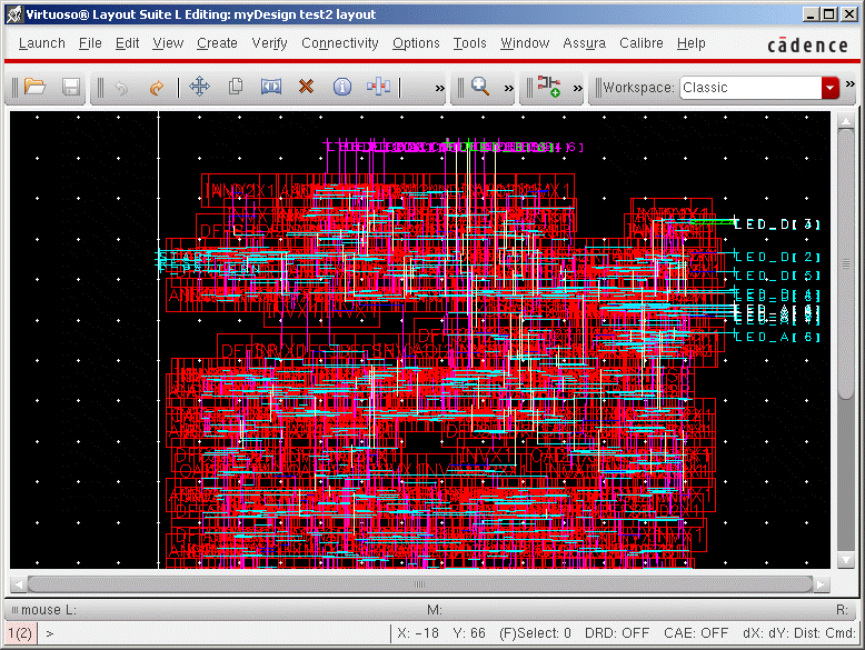
- Then a layout window will be shown as follows.

- Maximize the window and click 'Zoom to Fit' button in the toolbar.
- The current window shows standard cells and routed metals but you cannot see the details of standard cells. These abstract cells are called standard cell instances. To get a final layout, we need to load standard cells and replace standard cell instances by standard cell layouts. This is called 'flattening'.
- Choose 'Edit' -> 'Select' -> 'Select All' then all instances will be selected.
- Choose 'Edit' -> 'Hierarchy' -> 'Flatten...' and click 'ok' in 'Flatten' window with the default settings.

- The above snapshot was captured after flattening.
- Choose 'File' -> 'Save' to save your flattened design.
- Compare this layout with your encounter layout. Do those look similar?
Choose 'File' -> 'Export Image...' in the layout editor. Supported formats are bmp, jpg, png, and so on.
- 'LSW' window has visibility controls.
- If you click 'NV', only the selected layer will be shown.
- If you click 'AV', all layers will be shown.
- Click a specific layer with your center mouse button. This will toggle the visibility of the layer.
- After you toggle visibilities, you have to re-draw the layout to apply the changed visibilities. (Choose 'View' -> 'Redraw', or click 'Zoom to Fit' button in the toolbar)
- Choose 'Edit' -> 'Display Resource Editor...' in 'LSW' window. When 'Display Resource Editor' appears, choose any metal layer, change 'Fill Color' and 'Outline Color', and click 'Apply'. Redraw the layout to see if the new color was applied well.
- Here is the metal layer mapping. You will need this in 'Lab Problem : Generation of final layouts and
DRC' section.
- L49 - metal 1
- L51 - metal 2
- L62 - metal 3
- L31 - metal 4
- L33 - metal 5
- L37 - metal 6
- L39 - metal 7
- L41 - metal 8
- L43 - metal 9
- L45 - metal 10
Actually each metal layer has two different names. For example, metal 1 layer has two names - 'metal 1' and 'L49'.

