- Click 'Design' and choose 'Design Import...'.
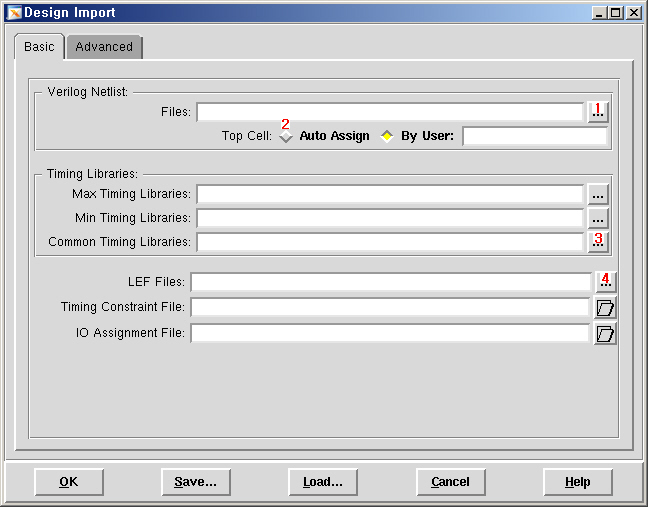
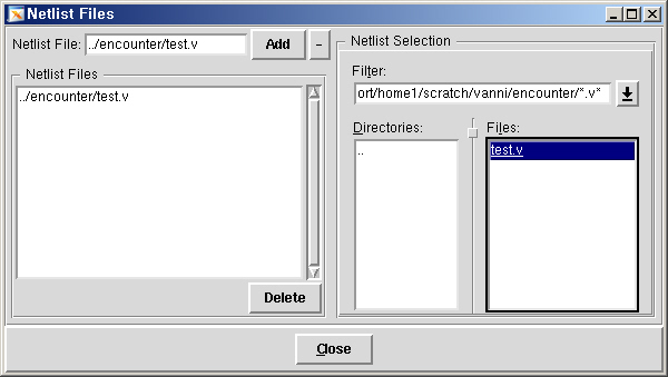
- Click the button '1', click the open button in 'Netlist Files'
window, add your netlist file (test.v) by double-clicking, and close the
'Netlist Files' window.
- Click the button '2' to make Encounter find the top cell automatically.
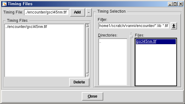
- Click the button '3', click the open button in 'Timing Files'
window, add 'gscl45nm.tlf' by double-clicking, and close the 'Timing
Files' window.
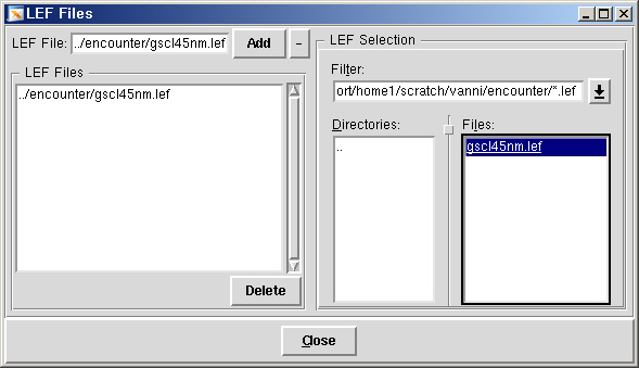
- Click the button '4', click the open button in 'LEF Files' window,
add 'gscl45nm.lef' by double-clicking, and close the 'LEF Files'
window.
- Your 'Design Import' window should look like the following.
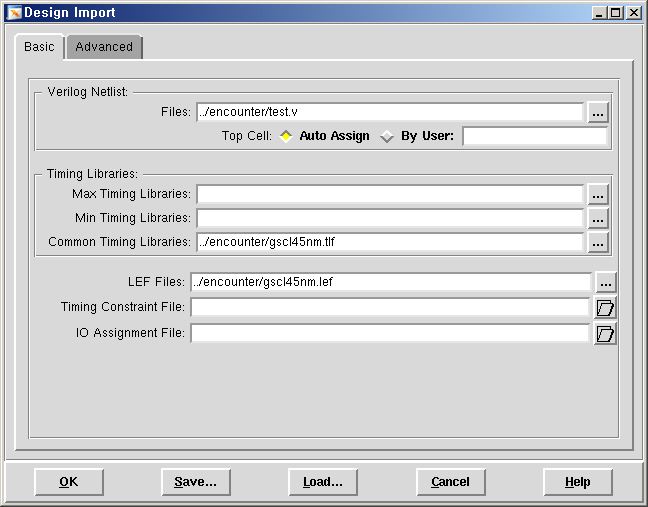
- Click 'OK' to import your design. Look at your command shell window. Encounter shows various information while it imports the design. The main window of Encounter will show you rows, where standard cells will be placed during placement.
In this step, we will set up layout area. We will not do floorplanning.
- Choose 'Floorplan' and then 'Specify Floorplan ...' in the main window
- In 'Basic' tab, you can specify core size by (1) AR (Aspect Ratio) or (2) Dimension. 'Core' is the region that cells are placed.
- Choose 'Dimension' under 'Core Size by', and set width and height to be 100. (100 by 100 is actually too large for this design. You will be asked to change the width and height later.)
- Choose 'Core to IO Boundary' and set 'Core to Left', 'Core to Top', 'Core to Right' and 'Core to Bottom' to 5
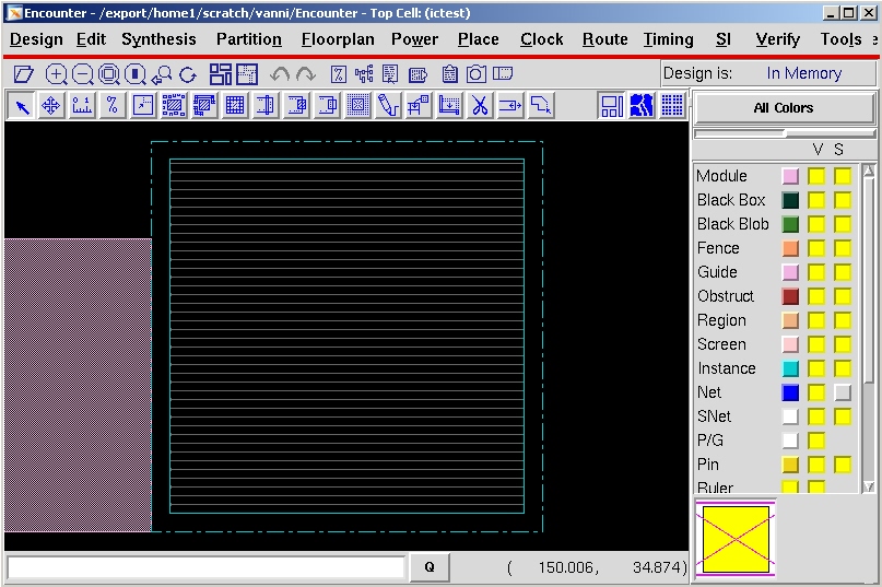
- Click 'OK' to finish and see the modified floorplan outline in the
main window. It should look like the following.
There is 'Place' menu in the menu bar but we will not use it because placement results done by clicking the menu are weird. Instead, we will use command shell window to do placement. However, you need to know what kind of options you have for placement.
-
Choose 'Place' -> 'Standard Cells And Blocks' then you will see
the following window.
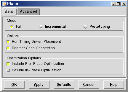
- Click 'Advanced Tab' and see 'Perform Congestion Optimization' and 'Specify Maximum Routing Layer' options. We will use these two options as well as the options in 'Basic Tab'.
- Click 'Cancel' to close the window. Do not click 'OK' or 'Apply'.
Now, go to your command shell window.
- In the prompt, type
- setPlaceMode -timingdriven -reorderScan -congMediumEffort -doCongOpt -modulePlan
- amoebaplace
- Encounter will do placement. After placement is done, click 'Physical view' button in the main window and see how standard cells were placed. The following figure shows an example
- In the physical view, click any cell and see the information of the cell in the bottom-right part of your window.
- To see the core utilization, click '%' button in the toolbar and drag and make a rectangle containing the core region. The utilization will be shown in your command shell window. It will be about 25% in this example.
- Choose 'Route' -> 'Nanoroute' -> 'Route...' then you will see the following window.
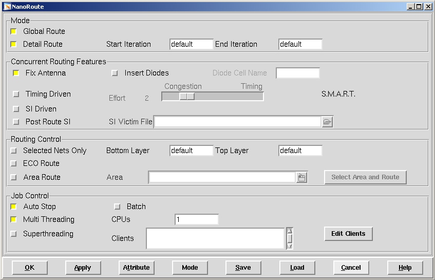
- Click 'OK' to do routing with default settings. Click 'Physical view' button
and see the routing result. It should look like the following.
- See your command shell window. It shows the routing information such as total wirelength, total wirelength in each metal layer, the number of vias, the number of DRC violations, and so on.
- How to capture screenshots: Choose 'Tools' -> 'Dump To GIF File...'
- Click the following small bar in the main
window.
- Scroll down and see the following items.
- You can turn on and off the visibilities of metal layers and vias. Turn on and off visibilities and see if it works well. You will need this to capture specific metal layers later.